
What are Infrared Emitters, Receivers, and Repeaters?
Do you wish you could hide your entertainment system in a less obtrusive view, share a Blu-ray player between two rooms or perhaps control your stereo's volume from anywhere in your house? This month's technical article is devoted to the technology needed to accomplish any of the above and more. We will provide the info and parts you will need to soup-up your existing remote control system for more functionality and sure-fire ways to outdo the Jones. Read on, tune in and don't drop that remote...
IR Transmission Theory
Infrared light transmission has been the standard for line-of-sight type A/V remote controls since the early 1980s. IR transmitters use near-infrared light which is just below the visible spectrum [Factoid: remote control IR transmitted signals can be seen with digital cameras and camcorders as appearing to be visible, purple light]. By using near-IR wavelengths, manufacturers can use cheap, plentiful, IR LEDs which are nearly identical to their visible-light counterparts save for emitting frequencies just below what the human eye can detect.
Unfortunately, infrared light as a transmission medium does have its drawbacks in the form of many other competing IR sources. The sun, light bulbs, fluorescent bulbs, fireplaces and in fact, anything that radiates heat, also radiates infrared light. Using IR for a remote now sounds like a recipe for disaster right? Wrong. Thanks to some applied modulation theory, the transmitted infrared signal will not be swamped by interference from other light sources.
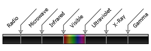
Electromagnetic spectrum
Signal Modulation
IR signals can be modified to blink at chosen frequencies high enough to to stand out over most atmospheric EMI. This is accomplished by modulating a signal with a sinusoid carrier signal of frequency between 30 and 100 kHz. [Factoid: you can test to see if your IR remote is working by using it while pointed at a AM radio tuned to static. You should hear an oscillating sound above the static if the IR remote is transmitting].
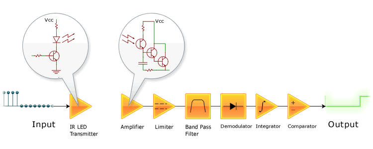
Block diagram of modulated IR transmission and reception
Older remotes with only a single channel used the presence of a carrier signal to engage a function. Later systems with multiple channels (for multiple functions: volume control, change channel, change input type, etc.) modulate the carrier signal with a different frequency for each function. These frequencies are separated out after the initial signal is demodulated with appropriate analog filters. Current IR remote systems transmit digital packets of data along a single carrier frequency. Digital data allows for simpler and less expensive filters as well as a smaller parts count using integrated circuits.
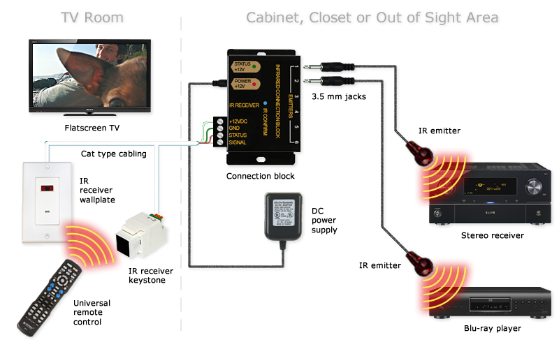
IR Emitters
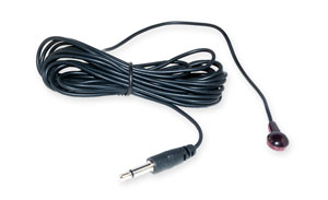
IR emitters are small wired transmitters for repeating an infrared signal from your remote to an isolated piece of A/V equipment. They are available in single or dual emitter packages with the latter emitting the same signal through two separate housings. Furthermore, infrared emitters also come in blink or blast-style transmission variations with the former being the most common. Blink-style IR emitters blink visibly as well as in infrared and are used to transmit data to a single component source. Blast-style emitters on the other hand, transmit data into several component sources at once and are used when space is a premium. Blast-type infrared emitters are considered a somewhat less reliable transmission method than blink-type.
IR emitters of each type are typically comprised of a mono, 3.5 mm jack attached to the red, plastic-housed transmitter end via a thin, 10 foot cable. The standard installation of remote IR emitters is to attach the transmitter end directly to the source equipment's IR window with self-adhesive. However, the transmitter end can also be placed several inches up to feet away from the receiver such as hidden on the inside of a stereo cabinet door or shelf.
IR Receivers
These devices pick up infrared signals from your remote control just like a TV or Cable box. After receiving an IR signal they encode and amplify it to be suitable for transmission via low-voltage wiring. IR signal receivers must be located in the room you wish to use the remote control since they require line-of-sight transmission. The cable from the receiver to the connection block needs to accommodate both signal data as well as power since the IR receivers are active devices. Using Category 5e or Category 6 wire (either UTP or STP varieties), remote signals can be transmitted several hundred feet without significant losses.
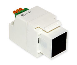
Keystone Receivers
These keystones are IR receivers which receive a signal from a handheld
remote control. Transmission is line-of-sight with a standard maximum
distance of approximately 15 feet (5 meters). However, IR transmission can
bounce off walls and other 'hard' objects to a certain amount.
IR keystones operate off 12 VDC and include three connections on their rear: 1) IR output signal; 2) +12 VDC; 3) ground. The signal as well as power connections are accomplished with solid-core Cat 5e/6 cable into the keystone's three tool-less, spring-clip connections on its rear. IR keystone receivers fit into standard keystone wall plates or even surface-mount boxes and patch panels. For more information on keystones and wall plates in general read our December 2010 technical article: Network Cable Connectivity.
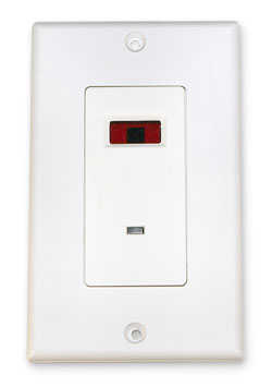
Wall Plate Receiver/Repeaters
These units are similar to IR keystone receivers but utilize an entire wall
plate for their space requirement. They do have one advantage over their
keystone counterparts in that they include a dual color status LED for
confirmation that the remote's function was received at the system end.
Because of this they utilize two pairs of Cat-type cable for the following
connections: 1) IR signal output; 2) LED status input; 3) +12 VDC; 4)
ground.
IR Distribution Over Coaxial Cable
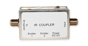
For users who do not currently have nor want to install extra lines of structured cabling in their household but still want an IR repeater cable system, IR distribution over coaxial cable may be the answer. This type of IR distribution system uses existing RG-type coaxial cable found in a home's walls. It operates by adding the IR signal to existing AC signals on the cable along with a DC voltage offset for power. For this system to work, users will need a minimum of one signal injector at the IR receiver source and a coupler at the emitter end.
The injector combines the IR remote signal with any AC TV signal already present on the coaxial cable line while leaving the TV portion of the signal unharmed. Additionally, the injector passes 12 VDC from the power supply to power any directly connected IR receivers. The IR signal is then sent up-stream to be decoupled by a direct injection IR coupler. The coupler also passes any TV signal through from its input to output as well as extracting the IR signal from the cable line for transmission through up to two connected IR emitters. Just as before, these emitters are connected directly to a system component's IR sensor. The couplers also have a port for connecting an AC to 12 VDC wall-wart to power the system.
Pitfalls of IR Coaxial Distribution Systems
Since IR distribution over coaxial cable adds a DC voltage on your cable line for powering the IR receivers, it can cause trouble in a number of scenarios. If a user's cable signal is provided via satellite (e.g., DirectTV or DISH Network) this system may not work. Satellite TV signal also adds a DC offset to their signal which may or may not be the 12 VDC required by the IR receivers. Another item to be aware of is that a DC blocking device or an injector (which also blocks DC voltages) is required for every component which is in-between the IR signal injector and the coupler. This applies to TVs, DVRs or cable boxes in the path which will short the IR distribution signal without a DC blocking element. Additionally, any cable splitter present in between the injector and coupler must be DC passing or else it will represent an open circuit for the IR distribution system.
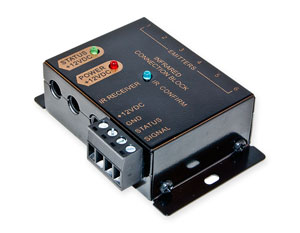
Connection Blocks
Connection blocks provide a place for connecting the IR receivers, emitters
and their respective power requirements. These devices typically support
multiple IR signal receivers which are all wired in parallel. Each receiver can be
provided with a return status indicator signal if applicable. Connection
blocks usually support up to six emitters which connect into the unit via
3.5 mm mono phone jacks. Most installations call for the connection block
to be located close to the emitters and the supported components such as
within a stereo cabinet or hidden out-of-sight in a closet. For convenience
connection blocks can be mounted directly to a wall or a shelf with screws.
Putting It All Together
The basic connection scheme for an IR repeater cable system is the same whether one
uses structured Cat-type cabling or coaxial cable direct injection: Remote
control signals are received by IR receivers (either discreet units or wall
mounted) and the signal is amplified and converted for transmission. From
here the signal is sent over either Cat 5e/6 cable or injected into RG-type
cable for distribution to the remotely-located connection block or a direct
injection coupler. The last item in either case is the beam emitters which
transmit the original IR beam directly to the remote-located components.
Users should gravitate to whichever system allows for access to pre-existing
infrastructure such as a cable line or structured cabling.
Sample IR repeater connection in home
End users living in newer homes with built-in Cat 5e or Cat 6 cabling for phone lines (less than two phones only) are in luck as this typically allows for a quick and painless install. Since the phone lines already share common wiring throughout the home, one can run the IR distribution system on the non-used data lines. In fact, IR remote signals as well as the 12 VDC can be inserted and extracted anywhere there is a RJ45 phone jack with this system.
| Signal line purpose | RJ45 pin | Cat 5e/6 wire color (T568A termination) | IR stand alone receiver |
|---|---|---|---|
| +12 VDC | 1 | white/green | Red |
| Ground | 2 | green | Black |
| Phone line 2 | 3 | white/orange | N/C |
| Phone line 1 | 4 | blue | N/C |
| Phone line 1 | 5 | white/blue | N/C |
| Phone line 2 | 6 | orange | N/C |
| IR Signal | 7 | white/brown | White |
| Return LED Status | 8 | brown | N/C |
With this wiring scheme you can add a 12 VDC power supply to anywhere in the home that is accessible to the above wiring as long as it occupies the first pair of wires (white/green and green). Additionally, one can add stand alone IR receivers which use 3.5 mm mono plugs to the system. This is accomplished by replacing the 3.5 mm mono plug with a RJ45 jack wired corresponding to the fourth column in the table above. By doing so one can easily add a IR receiver to any room with a RJ45 phone jack.
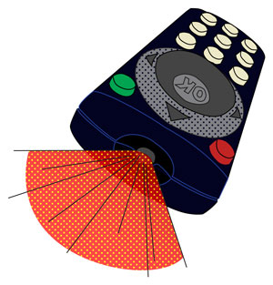
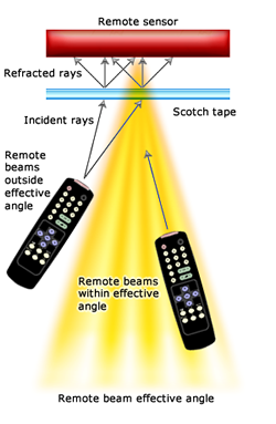
How To Increase Your Remote's Effective Angle
One chief complaint users have with IR remote controls is their
line-of-sight limitations. While this problem can be solved with many of
the IR extenders/repeaters described above for use across multiple rooms,
their use may seem to be overkill for use in a single room where the angle
between the remote and the associated receiver is too steep. Typical remote
control receivers allow for around a 60 degree reception angle in front of
the device. However, this angle can be drastically increased with a simple
fix that would make MacGyver proud: matte Scotch tape. Just apply a small
strip to cover the sensor on the IR receiver and enjoy a wider effective
angle for your remote control. The matte tape acts similar to frosted glass
in refracting incidental beams of IR light after
they pass through it. For non-geeks: this translates to generating many
beams of light, all at separate angles and at less strength than the
original light beam. This spread of refracted beams should be picked up by
the receiver within reason.
Silly Questions You Were Afraid To Ask
- Q:Why can I shoot my remote through clear windows but not walls?
- A: Infrared light, like visible light, is comprised of waves. These waves can penetrate transparent objects such as glass or clear plastic but may lose energy and due to refraction. Solid objects such as walls, ceilings, furniture and mirrors will allow a limited amount of reflection of an IR wave.
- Q:Can you help me program my VCR?
- A: Unfortunately, no one actually knows how to program those devices...
Terms and Definitions
- Active device: A type of circuit component with the ability to electrically control electron flow.
- Electro magnetic interference (EMI): An electromagnetic disturbance that degrades or limits the effective performance of electronic or electrical equipment.
- Infrared light (IR): Electromagnetic radiation with a wavelength between 700 mm and 300 um, which equates to a frequency range between approximately 1 and 430 THz. IR radiation is just below visible light on the frequency spectrum.
- Integrated circuit (IC): A miniaturized electronic circuit manufactured in the surface of a thin substrate of semiconductor material.
- Light emitting diode (LED): A semiconductor light source which are available in infrared, visible and ultraviolet wavelength variants. LEDs are becoming increasingly popular in consumer electronics, automobile and home lighting due to their high efficiency and long life spans.
- Line-of-sight propagation: This refers to electromagnetic radiation traveling in a straight line. These waves may be diffracted, refracted, reflected or absorbed by atmosphere and obstructions with material and in general cannot travel behind obstacles.
- Refraction: The change in direction of a wave due to a change in its speed as it passes through a medium.
- Sinusoid (a.k.a., sine wave): A mathematical function that describes a smooth repetitive oscillation. This function is commonplace in mathematics, physics, electrical engineering and many other fields. A sine wave�s most basic form is a function of time (t): y(t) = A ⋅ sin(ωt + φ)
- Structured cabling: A building telecommunications cabling infrastructure consisting of a number of standardized smaller element subsystems.
- Visible spectrum: The portion of the electromagnetic spectrum visible to the human eye. Electromagnetic radiation in this range of wavelengths is called visible light or simply light. Human eyes will respond to wavelengths from about 390 to 750 nm which correspond to a frequency band in the vicinity of 400�790 THz.